Chapter 9 Multiview drawings by darryl kring on Prezi. Ch8 multiview drawings CHAPTER 8 Multiview Drawings.

Exploring Drafting 11th Edition Page 227 227 Of 592
CHAPTER 8 Multiview Drawings 381 822 Horizontal Plane of Projection The top viewof an object shows the width and depth di-mensions.
. A primary view of a feature shows the feature in its true shape and size. Hole features on an angled surfaces that are inclined to the projection plane are drawn as _______ rather than in their true shape. Orthographic projection techniques can be used to produce both pictorial and multiview drawings.
Chapter 8 Multiview Drawings Mcgraw Hill Education 2018. Multiview Sketches Answer Key multiview drawing These views require hidden lines When engineers create drawings of cylindrical objects or objects that have holes they must represent their axes and axes points with centerlines Knowing how to sketch and interpret multiviews is an important skill for any engineer. CHAPTER 8 Multiview Drawings 83 ORTHOGRAPHIC PROJECTION 86 Orthographic projection is a parallel projection technique in which the plane of projection is positioned between the observer and the object and is perpendicular to the parallel lines of sight.
Editing Dimensions Chapter 10. Editing Features Chapter 10Advanced Modeling Tools-III Chapter 11. Chapter 9 Multiview Drawings Vocabulary Study Guide A.
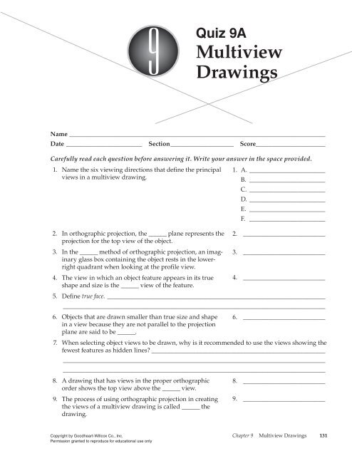
In a multi-view drawing a view in which an object feature appears in its true shape and size. The five main goals in delivering negative news are to 1 convey the negative news 2 gain acceptance for it 3 maintain as much goodwill as possible 4 maintain a good image for your organization and 5 reduce or eliminate the need for future. Models Mockups and Prototypes 19.
In orthographic projection the _____ plane represents the projection for the top view of the object. AutoCAD 2D Workalong 27-1. Are perpendicular to the profile plane.
Multiview Drawings Drafting vocabulary 9. A drawing that requires more than one two-dimensional view in order to provide an accurate shape and size description of the object being produced. Are parallel to the top plane.
What is the angle of projection from the slanted surface into the auxiliary view. Most drawings produced and used in industry are multiview drawings. Using the SAVEAS command save with the name.
Plotting Drawings Chapter 15. It is called a multiview drawing. Multiview drawings are used to provide accurate three-dimensional object information on two-dimensional media a means of communicating all of the information necessary to transform an idea or concept into reality.
Identify and explain positive and negative mass as it relates to an object. Chapter 2 Isometric Projection and Multi View Drawing s Below are the desired outcomes and usage competencies based on the completion of Chapter 2. 47 Multi-View Drawing Horizontal Lines Horizontal lines Are parallel to the frontal plane.
This preview shows page 1 out of 1 page. Working with Drawing View-I Chapter 15. Center a multiview drawing on the drawing sheet.
8242010 jcs Multiview Drawing. What Is The Purpose Of A Multiview Drawing. Assembly Modeling-II Chapter 14.
Surfacing Modeling Chapter 17. Dimension Styles Multileader Styles and System Variables Chapter 11. Using orthographic projection to lay out the views of a multiview drawing is known as _______ in the drawing.
A drawing that has views in the proper orthographic order shows the top view above the _____ view. New Syllabus Additional Mathematics Workbook New to the SpectrumR series Geometry is a skill-specific math resource designed to completely support and challenge sixth graders in geometry. Perpendicular to 1 Appear as true length in two Frontal and Top planes.
Understand Isometric Projection and 2D sketching. CHAPTER 8 Multiview Drawings 84 views must be equal. Template Drawings Chapter 16.
Advanced Modeling Tools-IV Chapter 12. A multiview sketch also referred to as an orthographic projection sketch is the standard sketch format used by engineers to communicate ideas to professionals in the building trades. Figure 89 The top view is projected onto the horizontal plane of projection which is a plane sus-pended above and parallel to the top of the object.
This 96-page book goes into greater depth. In the _____ method of orthographic projection an imaginary glass box containing the object rests in the lower-right quadrant when looking at the profile view. Online Library Geometry Chapter 9 3 class 10th in physics chemistry mathematics.
Right-side view Parallel to 2. Graphs and Charts 21. Identify various types of features existing within objects.
Model Space Viewports Paper Space Viewports and Layouts Chapter 14. Modeling Tools-II Chapter 9. Activity 25 Multiview Sketching Answer Key.
Orthographic multiview projection is a generally accepted convention for representing three-dimensional 3D objects using multiple dimensions 2D of the front top bottom back and sides of the object. Multi view drawing test answers. Working with Blocks Chapter 18.
AutoCAD 2D Lab 27-1. Identify the three main projection divisions in freehand engineering sketches and drawings. This is called orthographic projection.
Drawings Worksheets Teacher Worksheets. Appear as a point in the third. Check your answer in Figure 27-7.
Those who make their living building ideas require a different type of drawing format. Name the six viewing directions that define the principal views in a multiview drawing. To draw a two-dimensional view of one side of the object place a imaginary plane parallel to the side and project the view of the object perpendicular onto the plane.
The standards and conventions of multiview drawings have been. Multiview Drawing A multiview drawing is one that shows two or more two-dimensional views of a three-dimensional object. More in-depth look into the multiview drawings we will first look at the concepts and principles of projections.
Hatching Drawings Chapter 13. Front The process of using orthographic projection in creating the views of a multiview drawing is called _____ the drawing. Answers to Chapter 8 Review Basic HCC Learning Web.
Describe an effective method of constructing an auxiliary view even if you do not know the angle of. In practice the minimum number of views possible is used to describe all the details of the object. To explain this system of drawing the object shown in Figure 8-1 will be used in this module.
Architectural Drafting 25. Electrical and Electronics Drafting 24. Explain the difference between primary and secondary views of objects and features.
CHAPTER 9 TEST YOUR KNOWLEDGE p. Using construction lines and object snap tracking. Adding Constraints to Sketches Chapter 12.
Assembly Modeling-I Chapter 13. Object and Hidden draw a multiview drawing using the standard three views of each of the five objects in Figure 27-2 to 27-6. 6 Chapter 8 Multiview Drawings Welcome To.
Working with Drawing View-II Chapter 16. Figure Step 1 Step 2. List two methods of aligning the views in a multiview drawing.

Orthographic Projections Gmed Unit 1 Ppt Video Online Download
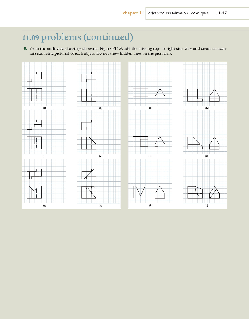
Solved From The Multiview Drawings Shown In Figure P 11 9 Chegg Com

Exploring Drafting 11th Edition Page 225 225 Of 592

Exploring Drafting 11th Edition Page 221 221 Of 592
Quiz 9a Multiview Drawings

Exploring Drafting 11th Edition Page 223 223 Of 592

Exploring Drafting 11th Edition Page 228 228 Of 592

Exploring Drafting 11th Edition Page 215 215 Of 592
0 comments
Post a Comment