Height of gusset plate 2002 4065345 mm Length of gusset plate length of base plate 550 mm Provide gusset plate 55034516 mm in size. Width of base plate Depth of the column section 2 thickness of gusset plate 80 mm to 100 mm.

Design Procedure Of Gusseted Base Design Of Column Bases Design Of Steel Structures Youtube
DESIGN OF GUSSETTED BASE Dr.

. In this example 65508 mm equal leg angle carrying 166 kN of tensile force is connected to the gusset plate by means of 5 mm thick fillet welds. Select a convenient width of the base plate. I Divide the factored column load by the design bearing strength of concrete and find the area of the base plate.
The allowable bending stress in the slab base is 185 Nmm 2 MPa. Axial load of column is 600 kN. In this case the base plate may be designed as follows.
Example 11 Design a base plate for an axial load of 60 kips and a moment of 480 in-kips. Gusseted Welded Base Plate. The recommended procedure to follow is to propose a size of the weld throat and to check whether it complies with the requirement of resistance.
N d 2 3 in B bf 2 3 in 2. Calculated stress distribution in a gusset plate Shedd 1934. Additionally Examples IIC-1 IIC-2 IIC-5 IIC-6 IID-1 and IID-3 all contain calculations for the Whitmore section.
Results for design purposes An example from his book is shown in Figure 9 which shows the calculated stress distribution in a gusset plate with a discontinuous bottom chord member at the panel point of a truss. It is assumed uniformly distributed under the slab. Dimension of gusset plate.
Bearing Strength of concrete06fck12Nmm2. Design of Steel Structures Prof. The size of the column is ISHB450.
Design the gusseted base. For this Reason Load Ratings of Trusses Have not Usually Included a Check of the Gusset Plate Capacity. The bolts are 15 from the edge.
It is welded to a 12 in. Here propose a 4 mm Design resistance for the double weld according to the simplified method is. B41 Design Procedure for a Small Moment Base 1.
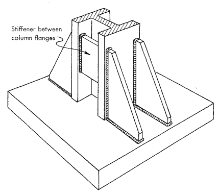
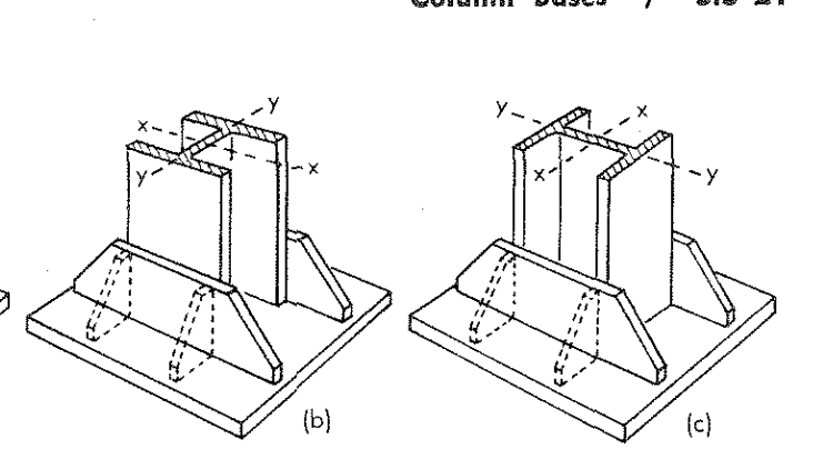
Area Reqd 2000x1031667x10 12 Length of base plate Column Depth 2 Cover plate thickness 2. Types of Column bases Slab base Gusseted base Slab Base Slab bases are used where the columns have independent concrete pedestals. Thick gusset plate using E70XX electrode.
288 People UsedMore Info. Area of slab base required. Design gusset for these loads.
The tension member is a 4 in. The gusset and beam web Example IIC-2 in the AISC Design Examples illustrates the pro - cess. M N 095d 2 n B - 080bf 2 3.
The allowable bearing pressure on concrete is 4 Nmm 2. 12a is considered as a final example. Make a section cut of the gusset pl the col face.
The design bending strength at the critical section Md12 f y γm0 Z e 12 f y γm 0 16t202 fγymt02 Now MMd w c2 2 02 f yt2 γm 0 tc25 wfγym 0 Where t is the aggregate thickness of base plate and cleat angle for bolted gusset base and thickness of the base plate for welded gusset base at the critical section. The structural member is an 8-inch wide flange and the base plate is 14x14. N14 A N125 8 60 k 480 in-k T fc 55 C A3 Fig.
To obtain load on reinforcing pl use max normal stress on above section and multply it by gusset thickeness to get line load on reinf pl. The optimum shape design of the gusset plate with welded connection shown in Fig. The design examples provide coverage of all applicable limit states.
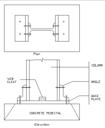
A thick steel base plate and two cleat angles connecting the flanges of the column. A Steel column of effective height 5m has to transmit an axial load of 2000KN. So this is how one can design a gusset plate when the column is under compression and moment okay.
Determine plate cantilever dimension m or n in direc- tion of applied moment. Convert brace load into shear and normal forces on this sectionNormal force will also result in a moment on the section. Consider the yielding and fracture of the tension member.
Example 122 A column section SC 250 856 carries an axial load of 600 kN. Truss Gusset Plates and Connections of Truss Members to the Gusset Plates are Ordinarily Stronger than the Truss Members to which they are Connected. Column bases are structural elements used in the design of steel structures to transfer the column load to the footings.
Design Examples V140 AMERICAN INSTITUTE OF STEEL CONSTRUCTION iii PREFACE The primary objective of these design examples is to provide illustrations of the use of the 2010 AISC Specification for Structural Steel Buildings ANSIAISC 360-10 and the 14th Edition of the AISC Steel Construction Manual. Load coming from top to bottom needs to transfer from steel to concrete o. To resist axial forces coming from top to bottom Column Base plates are designed.
Determine the design strength of the tension member and connection system shown below. Choose trial base plate sizes B and N based on geom- etry of column and four-anchor requirements. Fy for the plate and anchor bolts is 36 ksi and fc is 3 ksi.
N Rdwhor 2 wRd F l wRd vwd F f a 2 w M2 u vwd 23366 Nmm 085 125 3 430 3 β γ f f. Design a slab base for the column. Areas of Possible Confusion There are several predictable areas where confusion can arise in dealing with a Whitmore section.
Please Suggest Reading Materials For Designing Gusseted Plates For Moment Transfers Structural Engineering General Discussion Eng Tips

Design Of Column Bases Slab Base Gusseted Base Design Of Steel Structures Youtube

Gusset Base With Column Base Connection Youtube
Column Bases Design Of Steel Structures Civil Engineering Projects

Column Bases Design Of Steel Structures Civil Engineering Projects

Comparative Analysis For Economy Between Steel Slab Base And Gusseted Base Semantic Scholar
Design Of Gusseted Base I Design Of Column Base I Design Of Steel Structures Youtube
Please Suggest Reading Materials For Designing Gusseted Plates For Moment Transfers Structural Engineering General Discussion Eng Tips
0 comments
Post a Comment